KOLB SLINGSHOT CONSTRUCTION LOG
The following is my construction log for my Kolb Slingshot project. I worked on this project from 2000 to 2001 but did not complete the airplane. I've left this information here as reference for others. Hopefully it helpful to someone working on a similar project.
THIS PROJECT WAS NEVER FINISHED
I hate that it worked out this way, but Kolb stopped production of the Slingshot in the middle of my project. Kit #2 (of which I didn't have at the time) then became a "special order" and doubled in price. They did give me a window of 30 days at the old price, but I didn't have the cash right then. Left feeling not so happy about the company took the enthusiasm away from this project.
At this time of this writing, I still have the project... but I've moved on.
GETTING STARTED
My company just sent me to Nebraska for the next six months. I couldn't think of a better way for me to stay out of trouble than to build an airplane in my empty apartment.
Week 1 - February 13-19, 2000
Received two shipments for Kit 1. It was a little unnerving to receive the first half of the shipment without knowledge of the second. After unpacking, I asked myself "I paid $3000 for this?!" Fortunately, the second shipment arrived a few days later. No damage, no backordered parts, nothing missing.
 |
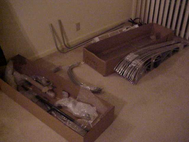 |
| Shipment 1 (delivered by common carrier) | Shipment 2 (delivered by RPS) Notice the completed ribs! |
 |
|
| Set up a worktable in my apartment. Very simple, two saw horses and a 36" wide unfinished door. The door works better than plywood or particleboard as it's flat and stays that way. |
TAIL FEATHERS
Week 2 - February 20-26 [ 4 hours total ]
Finished both elevators and started on one of the horizontal stabilizers.
I found it hard to make the elevators perfectly flat. If you’re just a few thousands off forward or back on drilling the rib rivet holes, the tip of the rib will be out of plane noticeably. I didn’t have this problem with tubing connected by gussets and multiple rivets.
I find that working without constructing a jig provides good results and speeds up the process. I just make marks on the worktable as an outline. To keep things square, I assemble the main components of the piece with the only one or two rivets per gusset so there is some movement. When I'm ready, I square up the piece and install the remaining rivets.
Week 3 - February 27-March 4 [ 3 hours, 7 total ]
Started the other horizontal stabilizer, both of which are now over half finished. Fabricating the gussets is very time consuming and not much fun. I would have paid to have all of these pre-made.
Week 4 - March 5-11 [ 5 hours, 12 total ]
Finished both horizontal stabilizers except for the hinges. I'm going to wait until the initial rigging to locate these.
The work on the vertical stabilizers was cut short after I pushed a drill bit 1/2" into my index finger. Before that happened, I found a way to build it without cutting a hole in the table. Also, the steel fixture provided by Kolb was off a few degrees. The lower vertical stabilizer was shortened about two inches by this inaccuracy. They weren't kidding when they marked the drawings with "cut to fit".
That brings up another complaint. None of the drawings are to a specific scale (i.e. 1/4" = 1"). Since there are several missing dimensions, I'm left trying to figure out how long to cut tubing.
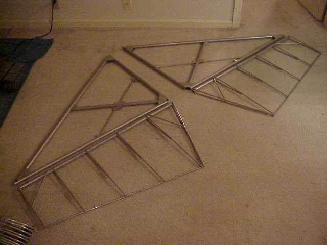 |
 |
| Horizontal stabilizer with elevators | Vertical stabilizer - The easiest way to assemble this is start with the main upright and work around to the steel fixture. Put only three rivets in each gusset and don't connect the last tube to the fixture. This leaves the whole assembly flexible. Do the same for the lower stabilizer, adjust so that the tailpost clearance is consistently 6", and complete the riveting. |
 |
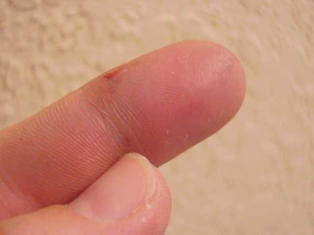 |
| Typical gusset construction | Stuck the drill from the edge of the finger down to where my thumbnail points. Hurt like hell but it still works. |
Week 5 - March 12-18 [ 0 hours, 12 total ]
Took the week off. This is to be a fun project, not a job.
Week 6 - March 19-25 [ 3.5 hour, 15.5 total ]
Finished the vertical stabilizer. Noticed that the nerves in the old finger are reconnecting.
I called Poly-Fiber about acceptable metal primers that work with the fabric adhesive. It's true that all but epoxy-chromate will be dissolved by that adhesive. But it is not necessary that the epoxy-chromate primer be sprayed directly on bare metal. For the small parts in the tail, I plan to prime with a good primer and cover that with the epoxy-chromate when get back to my shop. (I know this seems like a stupid extra step but I won't be home for three more months and I want to keep the project moving.) I will only do this where I need to protect the steel that I won't be able to get to after assembly.
Worked on the outline tubing of the rudder, used a five gallon bucket to bend the curves. Curving the top of the rudder is and art if you want the transition from the stabilizer to the rudder smooth. Completed the remainder of the rudder the next day.
Week 7 - March 26-April 1 [ 4 hours, 19.5 total ]
Started rigging the tail. The vertical stabilizer slipped on perfectly. The instructions suggested to use a straight piece of angle on the tail tube to find a line straight down the axis, but it's easy to twist this and spiral down the tube. I found that the tiny grooves left from the manufacture of the tube are perfectly oriented on my tube and used those.
First big mistake: I noticed that I had used the .035" tube to build the rudder as opposed to the .042". How frustrating because I did a great job on the rudder otherwise. After calling Kolb, I find that the Mark III and the Firestar both use .035" on the rudder. They increased this to .042" for the Slingshot because some will have Rotax 912 installed. I plan to use a Rotax 503 or 582 and was told that the rudder I have will work.
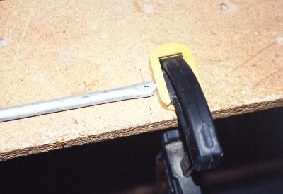
I have seen that other builders use a sheetmetal break to bend the tail attachment gussets. Don't waste your money. A vise and the flat of your hand will work with great results.
Installing hinges is not easy. Even with spacers to position the hinge, an inaccuracy where you predrilled the hinge could greatly affect the installation. I have worked with piano hinges in my cabinet shop and I can only come to one conclusion about Kolb's hinge selection: it's the least expensive solution. You can purchase these hinges predrilled (and very accurate) in a variety of hole patterns. It just costs a little more. My only other suggestion is to not use continuous hinge at all but a hinge similar to the method of attaching the horizontal stabilizer to the tail tube.
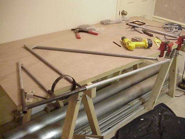
 |
 |
| Tail | Vertical stabilizer |
 |
|
| Note the temporary hinge installation. I used aluminum rivets that were coated white. They are easy to drill out and are not easily confused with the steel rivets due to the white coating. |
Week 8 - April 2-8 [ 5 hours, 24.5 total ]
Rigged the tail this week. I thought this process through and found that there is an easier method than that described in the instructions. The instruction would have you assemble all the components temporarily and then unassemble them. Meanwhile, you struggle trying not to drop or bend anything while things are partially attached. Although its a good idea to mount the vertical stabilizer, attaching the horizontal stabilizer isn't required.
You need to mount the vertical stabilzer to locate the attachment gussets and to drill the two 1/4" holes. If you have confidence in your math and measuring skills, you can leave the horizontal stabilizer alone. Mounting the horizonal stabilizer is done to accomplish two things, to locate the forward attachment hinges on the tail tube and to locate the steel hinge tubes into the ends of the elevators.
The forward attachment hinge was located by laying out the hoizontal stabilizer and it's half of the attachment hinge on the worktable as described in the drawings and measuring the distance from the hinge to the elevator hinge line. My distance from the hinge line to flange of the aft hinge bracket was 27". As the hinge line and the 1/4" hole in the tail tube are centered when assembled, I then measured 27" from the 1/4" hole to position the first hinge bracket on the tail tube. Using the AN hinge bolt to determine offset spacing, I located the second hinge bracket. I did this for both the left and right attachment hinges.
The steel hinge tubes took a little more math. Essentially what you want to know here is how far to insert the steel hinge tubes into the elevator tubes and where to rotate them. First you need to calculate the distance from the end of the back tube of the left hoizontal stabilizer to the right. As the back tube and the elevator tube are flush, this will be the same distance between elevator tubes. Start with 6" for the tail tube, add 2 x 1-1/4" for the attachment hinges, and add 2 x 3/4" for the gusset notch on the horizontal stabilizer (actually measure these distances as yours may be different). This gives 10". Now assemble the elevator horn with the steel hinge tubes and mark them 5" (1/2 of 10") from the center of the horn. That's how far to insert them. Next, dissasemble the horn and insert two pieces of scrap 5/16" tube, enough to determine if the horn ends are twisted. Mine were out of alignment a few degrees. Remember this error, if any. Now place your elevators on the floor (or work table), and insert the steel hinge bracket up to the mark you made. Insert the scrap 5/16" tube into the ends of the bracket and rotate until the scrap tubes are parallel with the floor. Now twist them to match any error that your horn bracket had. Drill and rivet and your finished.
I used this opportunity to double check all tail pieces to make sure I didn't miss and rivets or anything. Next time I'll work with these parts is during covering and I won't be focused on the completion of assembly. (Sure enough, I missed the 3/16" holes for the guide wires.)
Week 9 - April 9-15 [ 0 hours, 24.5 total ]
Took the week off.
Week 10 - April 16-22 [ 0 hours, 24.5 total ]
Took the week off.
WINGS
Week 11 - April 23-29 [ 4 hours, 28.5 total ]
It will be quicker to build both wings at the same time if I have the room. This way, I only prepare once for any operation. Also, any deviation from the plans (read: mistake) will be identical on both wings.
Cleaned and painted the H-sections and installed them into the two wing tubes. I did not install these as described in the plans. Their method is conservative and very time consuming. If you have bad eyes, marginal assembly skills, or if your H-section is not perfectly flat, I would suggest following it. Otherwise here's an alternative: Draw your axial lines, top and bottom, on the main tube and drill the 1/2" holes as described in the plans. Install the H-section and the bolt and line up the assembly by looking into the main tube. Drill one 1/8" hole 6 1/4" from the center of the bolt on your line but go through the main tube only. Remove the H-section. Where you just drilled will have left a mark on the H-section tube. Drill through the tube at this mark but on the apex of the tube. Reinstall the H-section and rivet the assembly using this hole. The H-section is now aligned. You can place the other three rivets by just drilling through on your apex lines.
Don't install all the other rivets for the H-section. Although the instructions say to do it now, you'll have a difficult time installing the two surrounding ribs.
My ribs came assembled and taped together in a stack. At this time, I marked and drilled all the holes for the covering rivets. It took an hour this way but I would hate to think how long otherwise.
Week 12 - April 30-May 6 [ 1 hours, 29.5 total ]
Slipped the ribs onto the spar for both wings. They all went on smoothly except the ones that had to slide over the H-section rivet. I can't see how these would go on with all the H-section rivets in place.
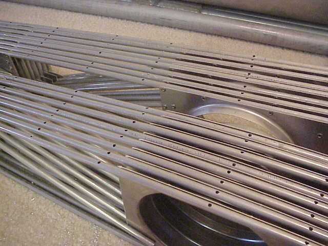 |
 |
| Ribs with cover holes predrilled | Ribs fitted onto spar |
It became evident after assembling the wing that there was a problem with my drag strut mount on the welded steel rib. The instructions say that if they are a little out of line they can be bent but one was much worse than that. After conversation with Kolb, I found that I had the inboard rib for the Mark III. It has a longer wing and the angle is different. A replacement was sent.
 |
|
| Foreground drag strut mount will require very moderate adjustment. The one in the background will require replacement. |
Week 13 - May 7-13 [ 0 hours, 29.5 total ]
Took the week off.
Week 14 - May 14-20 [ 0 hours, 29.5 total ]
Took the week off.
Week 15 - May 21-27 [ 3 hours, 32.5 total ]
Finally got back to work now that things have slowed down with my other projects. The first hour I wasn't very productive due to the fact that I had forgotten where exactly I was on these wings. I think I would rather just take several days off and finish this area.
I did purchase a digital level. It was a little hard to find as traditional hardware stores don't carry them. I had to go to a contractors supply store. After becoming familiar with the level, the accuracy is the same as a standard level and that could have been used with the same results. The digital level will come in handy during final rigging. Anyway, I own a new toy.
The wing was aligned pretty much how the instructions say to. The first step was to orient the H-section with the inboard rib upright. Simply visually aligning by looking into the tube was accurate within a few degrees. This would have been acceptable. I opted to insert a tube into the spar bolt hole and align that vertical. Then the rib was aligned horizontal. The inboard rib was riveted.
The second step was to position the outboard rib horizontal as well. This is where any twist in the wing would be induced so I double checked. That rib was riveted. With those ribs in plane (no pun intended), the others could be aligned using the rear spar.
 |
 |
| By inserting a tube into the through-bolt hole in the spar and using a level, the spar was oriented vertical. The inboard rib, resting on the sawhorse, is horizontal. (The ribs on the spar are loose and not aligned) | Once the inboard and outboard ribs were aligned and riveted, the others could be aligned with the rear spar. |
 |
 |
| Using a wide piece of paper wrapped around the spar and pulled tight, the rib is squared on the spar tube. | Murphy's law strikes again... At the third rib, the drag strut passes very close to a vertical stiffener. Of all my ribs, only one had that gusset too far forward and of course, it ends up installed as the third rib. |
Another obvious mistake: I made my marks for the location of the ribs from the outside of the inboard rib. These should have been from the inside of the inboard rib. Consequently, the ribs are all inboard 1/2". This comes into play with the drag strut and its interference with the ribs. The third rib had to be modified anyway so this wasn't an additional problem.
Had to replace the rivet tool this week, the teeth that pull the rivets were worn smooth. Not a problem since I bought the tool at Sears and it has a one year warranty. I figure that I will at least replace it again before the project is over.
With the rear spar riveted in place and the ribs riveted once at the main spar, I attached the front spar. I can then complete the rivets on the main spar. I did this to decrease any induced stress on the ribs. My fear was that I would make an error between the rear and main spar causing me to choose between a misalignment at the front spar or bending the rib slightly to account for the error.
Week 16 - May 28-June 3 [ 3 hours, 35.5 total ]
There is plenty of rivets that need to be installed to complete this wing and that's what I have been working on. I only have a few more weeks left before I have to transport everything back to St. Louis so I need to get moving (pun intended).
Primed the replacement left inboard rib and am ready to start on the left wing. I'm not near complete with the right wing although it's to a point where it can safely be transported.
Week 17 - June 4-10 [ 5.5 hours, 41 total ]
Started the left wing and included the 1/2" rib spacing error to match the right wing.
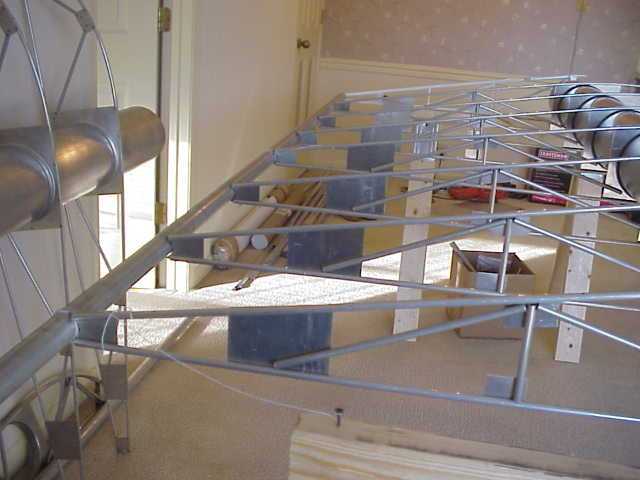
Attaching the ribs and front and rear spars went much faster with the second wing. At this point, both wings have the inboard eight ribs attached (if I complete the wing, I won't be able to get them out of the apartment).
 |
 |
| Left wing started | Both wings partially assembled |
To continue working, I started riveting the remainder of the wing out. The H-sections and inboard ribs at this point were only minimally attached.
As I was riveting the left inboard rib, I noticed that the tab that extends into the spar didn't seat right. It was welded incorrectly and Kolb will be sending a replacement. Unfortunately, I will now have to drill out 20 or so rivets.
 |
 |
| H-section rivets... Installing these after the ribs makes it easier to work with the ribs. Also, no rivets are under the rib flanges. | The inboard rib tab was welded incorrectly. Notice the gap between the tab and the spar. The remainder of the rib is otherwise true with the spar. |
This spar tab situation got me to do a little calculations on the forces of the attachment points of the wings. The most notable is that all the weight of the airplane and then some is carried on the wing strut. Since the center of lift is somewhere between just outboard of the wing strut attachment point and at the attachment point, lift generates either a downward force or no vertical force on the inboard spar attachment. It's opposite of what you would think. The major force on the inboard spar attachment is the reaction load due to the angle of the wing strut. This load pushes the spar inboard. Drag on the wing invokes a load on the drag strut attachment point but decreases the compression load on the inboard spar attachment. Of course, this is true only for a +G loading.
In a +4G load at gross weight and not turning, the tension in the wing strut is 3000 to 3500 lbs, the compression on the inboard spar attachment is maybe 1700 to 2000 lbs, and the compression on the drag strut attachment point is maybe 300 to 500 lbs.
The values shown above are for conversation ONLY and are not approved for design.
Now with that out of my system... Continued riveting the H-sections and the good inboard rib. It's very helpful to hang the wings on the ends of the saw horses so that the H-section is easy to get to (as shown in the above pictures). Plus any metal shavings fall away and don't get caught between the H-section and spar.
 |
 |
| The clearance between the drag strut and rib #2 was only 1/16". I expect that if I would have left it as is, vibration would have chaffed the two. | Relocated the stiffener on rib #3 as well. |
More Mark-III parts: The drag strut braces had me confused. After some twisting and turning, I surmised that I had the braces for the Mark-III. Kolb verified this and are sending the replacement parts.
 |
 |
| The brace for the Mark-III doesn't fit on the SlingShot. | The correct brace. All the drill holes were laser cut making the installation easy. |
Week 18 - June 11-17 [ 2.5 hours, 43.5 total ]
Installed the drag strut brace and finished out the rivets for the H-section for both wings.
Since I had already installed the inboard ribs, there was not enough open area at the end of the tube to insert a board to push on the H-section. This wasn't a problem except for the last inboard leg, it was the only leg that was pulled away from the spar tube. To pull this flush, I used a #6 drywall screw. After I drilled several 1/8" holes, I used a slightly smaller bit, inserted it into a hole in the middle of that group, and drilled through the backside of the H-section tube. I stacked several washers on the drywall screw and carefully screwed it in. The #6 drywall screw will not bite down on the 1/8" hole but it will on the smaller hole and it will pull the H-section against the spar. I only had to do this once and was then able to complete that leg.
Project Suspended [ 0 hours, 43.5 total ]
I have the wings complete to the point where they can be transfered from Omaha to St. Louis. Once I get home, I have many other projects to complete, the most important being the completion of a shop to continue this project. It may be a few months before I make any progress with the completion of this airplane.
WINGS AGAIN
Week 19 - October 8-14 [ 5.5 hours, 49 total ]
The inboard rib saga continues... Since I have moved back to St. Louis, no progress has been made with the project. In the next month, my wife and I are going to move to Southern Illinois so I haven't been real motivated to get everything set up. The only problem is that I have have a left inboard rib that I promised Kolb I would return.
I pulled the replacement out of the box and what do you know, the replacement left inboard rib had the same flaw as the one I had installed. The mounting ring and the gusset support tab were not squarely welded. This leaves me with the conclusion that the jig Kolb is using is not right. Regardless, I primed the replacement, drilled out the 48 rivets and removed the old one, cleaned up the edges, and installed the replacement.
This time, I mounted the support tab flat against the tube and left the end ring crooked. I won't win any trophys this way but it's now structurally correct.
A few days later, I installed the outboard end tube. It was cut so that it could be installed differently than the instructions show. As opposed to having the outboard tube butt against the rear edge tube, the outboard tube was long enough to move it to the end of the rear edge tube. This gives a smoother rear corner and another 1" of wing.
 |
| Crummy place to work |
 |
| The end ring and support tab are not square for the second time. |
AILERONS
Week 20 - December 10-16 [ 4.0 hours, 53 total ]
Moved again!
November and December was spent repairing the house we were moving to, moving everything we owned to Southern Illinois, and preparing the old house to sell. Yuck! Now that we have settled in, I can start on the SlingShot... again.
I received the new instruction manual from TNKolb. It is much better than the old one.
I spent a little time cutting the short tubes for the ailerons. Now that I am at home, I have access to all my tools. I set up my miter saw with an old blade and quickly cut the 60 rib tubes. Using the saw and a stop block this took no time and did a very good job.
Saturday I flattened and sanded the ends and drilled all the holes. I then assembled the bottom of the left aileron. I used a chalk line to mark the drill line on the 1 1/4" tube. This can be done if the tube is straight. What I learned from the tail assembly is that you are not assured a flat surface until the top rib tubes are riveted to the bottom tubes. Although the bottom came out pretty flat, I know any irregularities can be fixed when attaching the top.
 |
 |
| Setup in the basement. I can only do piecework here, there's no door to move the wings in and out. | Hole locations on the 1 1/4" tube marked using a chalk line. Set the chalk line on one end and sight down the tube like a rifle to position the other end and then snap the line. |
 |
 |
| For determining a 3/16" distance from the edge for the hole location, I marked a line on the table. After a while, 3/16" can be eyeballed without the jig, which is much faster. A drill press would be best. | Halfway completed aileron. There is a slight amount of bow to this one (which really can't be seen here) but this could be fixed when the top ribs are attached. |
Week 21 - December 17-23 [ 3 hours, 56 total ]
Assembled the bottom of the right and prepared to complete the top of both ailerons.
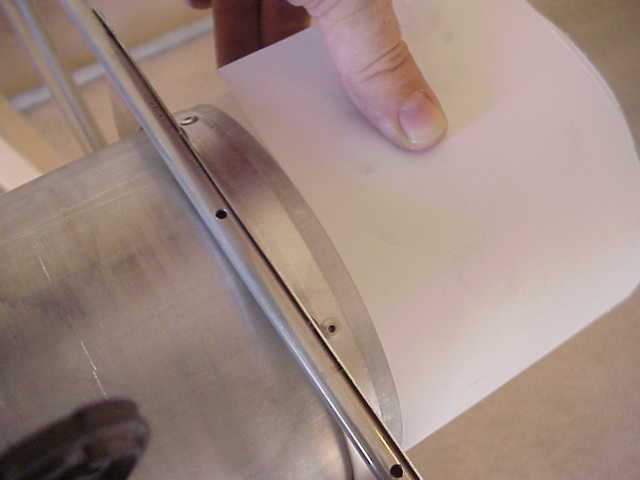
I used the digital level to determine the flatness of my worktable and found that it varied with twist a few degrees. I still had the door that I used in Nebraska and set it on the worktable using shims to keep it from twisting. This provided the flat surface for the final aileron assembly. Due to irregularities in hole locations, tube smashing, rear edge tube bend and twist, or hole alignment, the 5/16" tubes are not perfectly parallel. Since metal has an amount of spring to it, to simply hold it to a flat surface when doing the final assembly won't guarantee a flat part. To account for this, I developed a method that worked really well.
When riveting the bottom and top 5/16" tubes, the last rivet is the crucial one. The last rivet determines the geometry of the triangle that is made and therefore can be used to align the tubes. The best location for the last rivet is the connection between the bottom and the top tube. This way, any adjustment won't be as noticeable as it would if it were located on the 1 1/4" tube. The rivets into the 1 1/4" tube were made and the hole through the bottom 5/16" tube was drilled but the hole into the top 5/16" tube was not done. With the aileron upside down on table, the top and bottom tubes were pinched in my fingers and pressed flat against the table so I could drill the top tube using the hole in the bottom tube as a guide. For the sections were there was a twist or bow in a group of tubes, I corrected by shimming and clamping the section of aileron that was completed and overcompensated when I pressed the pair of tubes against the table to drill the last hole. When you do this, you can feel the tubes in our fingers slide against one another. As you attach the tubes from one end of the aileron to the other, check for flatness and if any overcompensation should be continued.
Using this method, the ailerons were within 1/2 of a degree of flatness.
Primed and installed the aileron counter-balances but didn't install the weights. Although the plans say to do this now, I want to balance the ailerons with the covering, paint, and control horns installed. At this point, the ailerons are finished except for the control horns, which will be installed during rigging.
 |
|
| All top and bottom ribs are riveted with the exception of the one the drill is pointing at. The five ribs in the background are shimmed with a length of scrap tube elevating the remaining ribs. The unriveted rib in the foreground required correction, which now can be done by pushing it down while drilling the last hole. |
WINGS COMPLETED
Week 21 - January 7-13 [ 9 hours, 65 total ]
With the tail surfaces and ailerons complete, the only remaining parts of Kit 1 is the wings. These are mostly completed and looking very much like wings but several details need to be finished.
The outermost ribs on both wings have 3/4" angle attached to stiffen those ribs. Unfortunately, the pick or shipping list listed 1/2", an error not yet discovered by TNKolb. I called TNKolb and they will be sending the 3/4" replacement and, hopefully, updating the pick list. To keep things moving, I planned to install the rib without the angle and will install that once it gets here.
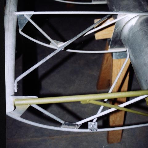
Monday, I started on the left wing. The drag strut was installed and the 2nd and 3rd ribs were modified as on the right wing to accomodate the rib misplacement and clearance problem (see previous write-up for more information). I also installed the drag strut brace, the inboard rib nose tube and trusses, and wing braces at the inboard rib nose.
 |
 |
| Wing braces at the inboard rib | Rib nose tube and trusses. Note how the design of the inboard rib does not match the drawings. |
I started on the bottom false ribs and noticed that the connection point on the main spar is right at the bottom. Care was taken when installing the full ribs so that no rivets were placed there as it weakens the spar. Putting a rivet there to connect the false rib would have the same effect. As an alternative, the bottom false ribs are long enough to wrap around the spar and the rivet point could then be a few inches back, just like the connection points on the full ribs. To accomplish the bend, I tried several methods and the one that worked the best was to hand bend the tube. This is easy to do with the exception of holding on to the tip of the tube. To do this, I drilled a 5/16" hole in a scrap of wood and insert about 1/2" of the tube. I then form the rest of the curve by hand. This takes a time but I think it's worth it.
Wednesday, the replacement 3/4" angle arrived. Fortunately, I had not installed the outermost ribs yet so I could do this work on the bench. I started this work and realized that it is impossible to install the ribs with the angle attached. The angle flanges are in the way of the rivets that connect the ribs to the leading and trailing tubes. So it becomes necessary to install the ribs first, then the angle.
Thursday, the bottom false ribs and the outermost full rib with angle are complete on the left wing.
Friday, I started on the upper false ribs. It took me a few ribs to determine a fast system but it works well. I took one rib and determined where the three holes should be. The two on the back are critical as you want to be off of the top of the spar 1 1/2" with the first hole and the second still on the spar. The top false ribs have a few inches of slack on the back that does not touch the spar. I used this one rib to mark all the others and predrilled and debured the batch. Deburing is critical on these as they rest on the spar. My false ribs were overbent so they needed to be flattened on installation. Using a level as a straight edge positioned only a few inches away from the leading edge, I connected a pair of ribs to the leading edge tube. I did this for all the bays (or sections between the full ribs). Then for each bay, I moved the straight edge about 6" away from the leading edge and flattened the false ribs even with the full ribs. I used a pair of quick clamps to hold the straight edge. This acon lifted the part of the rib with the rear holes away from the spar. I pushed this down and drilled the first hole. I then did this for all the ribs moving the straight edge when needed. I walked around to the rear of the wing, removed any shavings, and riveted all the first holes tight. From the rear of the wing, I could then rotate the rib plumb, drill the second hole, and rivet. In hindsight, it might have been even faster if I had a 4' or 8' level and position that only once or twice. We'll see on the right wing.
A side-bar note: The top ribs went much faster than the bottom even though there were twice as many ribs. This is due to the fact that I batched the jobs for the top and did the bottom ribs one at a time. This is the main reason I am working as fast as I am. It is so much faster to pick up the drill and drill 20 holes as compaired to picking up the drill 20 times to drill one hole each time. You get the point.
The rear rib flanges for the ribs on the wing tips were not included with the kit. TNKolb is sending these. With the exception of the wing tip, the left wing is done.
I installed the bottom false ribs on the right wing and used a 2" strip of 3/4" plywood long enough to span half the wing. Like the upper false ribs on the left wing, this went much faster. I also got pretty good at curving the back end of the rib by hand. I also installed the drag strut brace, the inboard rib nose tube and trusses, and wing braces. The upper false ribs are predrilled but I ran out of 1/4" rivets, most likely due to the fact that I wasted about 50 on the bad steel rib in November.
Week 22 - January 14-20 [ 1.5 hours, 66.5 total ]
I purchased rivets over the weekend and the upper false ribs were installed. Not having the rear rib flanges from TNKolb yet, I opted not to continue with the completion of the wing tip of either wing. This will most likely happen once the next kit arrives and I am ready to start again on the project.
 |
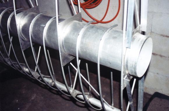 |
| Completed ailerons and wings (with exception to the wing tips) | Upper false ribs |
FUSELAGE
Week 23 - March 18-24 [ 4 hours, 70.5 total ]
Well, I'm complete with the wings, but I planned on selling the wings to finance my other projects. I didn't think I had the money for second kit which would be the fuselage and remainder of the kit.
Then I started thinking, I've got to weld up a fuselage for my Super Ace so why not build this one too. I designing one on CAD at work and it looks pretty good.
 |
| Drawn on CAD where the yellow lines are 5/8"x.035, the green lines are 3/4"x.035, and the purple lines are 7/8"x.049. The basic dimensions are about the same but I added a few inches here and there. I also plan to add gear with bunge cord shocks. |
April - November 2001 [ 0 hours, 70.5 total ]
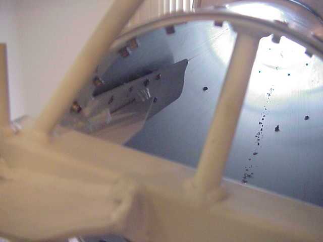
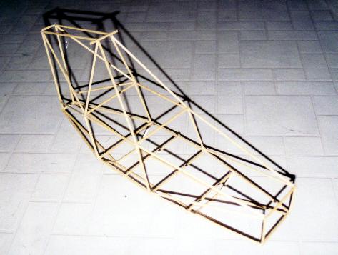
It's fall and I haven't done anything. I've been working on my Model-A. Although, I did make a proof-of-concept model just to see if what I drew was appropriate.
 |
|
I used this model, made from 1/8" dowels and hot-melt glue, to check the structure. It has a few spots that are not trussed properly and there are some weaknesses. Back to the drawing board. I suspended this project. Not because I don't want to finish it, it simply got moved back in the list of priorities due to wife, kids, and an new old house to work on. THAT'S ALL... THIS PROJECT WAS NEVER FINISHED PARTING SHOTS... in the spring of 2013 the shop was cleaned out and what was left of this project was sold for scrap. I thought it was fitting that the child that my wife was pregnant with when I started this project should be the one who got to strip the steel from the aluminum. Life moves on. 
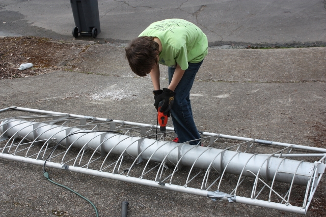
And off to the scrap yard: 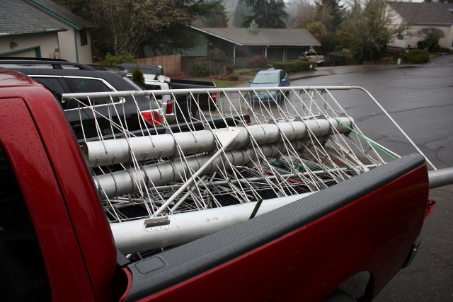
|